Die-cutting teams face a stubborn trade-off: more sheets per hour can mean less time to catch drift, crushed edges, or incomplete cuts. In automatic flatbed die-cutting, the result depends on more than press speed. Board grade, make-ready quality, stripping setup, and operator checks all affect output. A job may look perfect for the first ten sheets, then wander.
Industry research helps explain the pressure. Smithers’ The Future of Global Printing to 2028 examines changing print demand and production economics, while PMMI’s 2024 State of the Industry report discusses operational pressures facing packaging machinery users. These reports provide useful context, not a universal speed setting for every die cutter. Machine conditions vary. That matters.
So, how to balance speed and precision in automatic flatbed die-cutting? Start with measurable checks: register consistency, cut depth, waste removal, and stable delivery—not the speed display alone. Watch a real run: a sheet enters, the die closes, and the waste skeleton lifts cleanly. If defects appear, record where and when they occur before changing settings. A small slowdown can prevent a full pallet of rework. Still, no single adjustment fixes every job; that is an easy claim to make, and a hard one to prove. The five approaches below focus on practical setup, process monitoring, and controlled speed increases, helping teams protect cut quality while improving throughput.
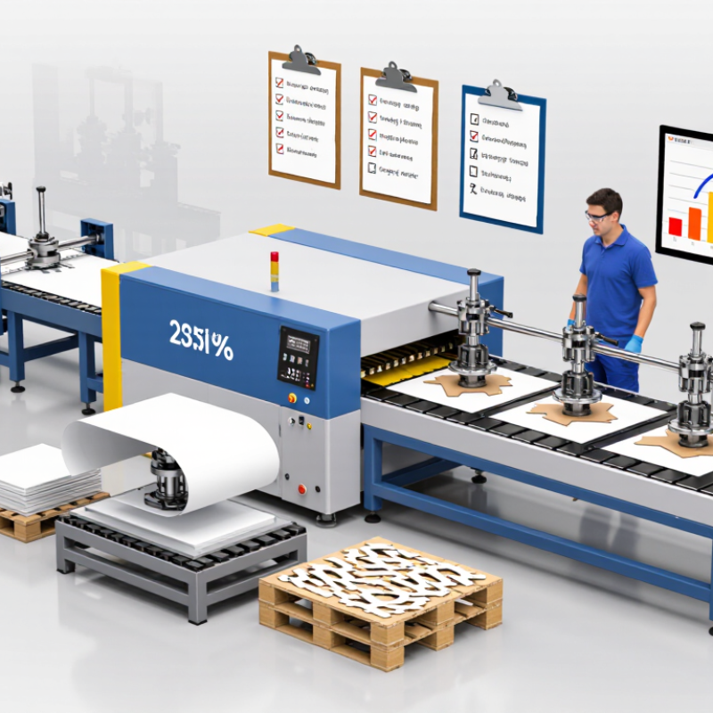
Set the tolerance before setting press speed. ISO 2768-1:1989 lists a medium general tolerance of ±0.3 mm for dimensions from 30 to 120 mm, and ±0.5 mm from 120 to 400 mm. These are reference values, not die-cutting guarantees. Specify the actual feature, material, and measurement method on the job drawing. A small notch beside a fold may need a tighter limit than an outside edge.
Track good sheets per hour, not just machine strokes. For example, 2,400 acceptable sheets per hour at a ±0.2 mm cut tolerance may outperform 3,000 sheets with frequent rejects. Check a sample at startup, then measure several points across the sheet. Paper grain, board thickness, and tool wear can shift the cut. That target may be optimistic; record real results by material and job setup.
Tips: Log tolerance and good sheets per hour together. If drift appears, reduce speed in small steps and recheck the cut. A quick check is not enough. Keep the rejected sheets in the record, too.
Die clearance should match the stock’s caliper, not just a machine’s usual setting. Measure several sheets across the stack; coatings, moisture, and compression can make similar stock behave differently. For paperboard, a gap that is too tight may crush edges or mark the face. Too wide, and fibers may remain attached, especially on small details. Small changes matter. Run a short test at the intended production speed, then inspect cut edges and waste release under consistent lighting.
Grain direction needs a separate check. It affects how paper folds, splits, and springs back, so a cut near a fold may behave differently when rotated relative to the grain. Keep grain orientation fixed while adjusting clearance; changing both variables at once makes defects harder to diagnose. Compare samples with a loupe, check narrow bridges, and feel for rough fibers. A clean first sample can still mislead. Recheck after the stock acclimates and after the die warms during a longer run.
Run controlled speed trials on the same stock, die, and job layout. Test three press speeds, such as 80, 100, and 120 strokes per minute. Hold each setting long enough to include startup and steady production. Short samples lie. Record total blanks, accepted blanks, scrap, stoppages, and setup adjustments for every run.
Calculate good output per hour, not just machine speed. Divide scrap pieces by total pieces to find the scrap rate. For example, a trial producing 9,300 acceptable blanks from 10,000, with 700 rejected, yields a 7% scrap rate. Compare that with a slower run’s usable output. A faster setting can look impressive while producing more edge tears, misregistration, or incomplete cuts. Keep inspection criteria consistent, and note whether defects cluster near the beginning or end of a run.
Deloitte and MAPI’s 2023 Smart Manufacturing Survey found that 86% of surveyed manufacturing executives expected smart manufacturing initiatives to be a primary competitiveness driver within five years. That is not a die-cutting benchmark, but it supports measuring process performance rather than trusting intuition. Review results by shift and material lot, too. One trial may be skewed by a worn rule or uneven stock. That is an inconvenient caveat, but worth recording.
Set a job-specific registration target before the die reaches the press. For a detailed label or layered carton, ±0.1 mm may be appropriate, but it is not a universal standard. The right tolerance depends on artwork, substrate, die condition, and how misalignment affects the finished product. A small shift can expose an edge or leave a narrow border uneven. Small shifts matter.
Confirm the target against a physical sample, not just the file. Run a short setup batch, then measure registration at several points with a calibrated loupe or vision system. Check the sheet near the leading edge and the far side; web tension or sheet movement can create different errors across the same run. Record the readings alongside press speed, material lot, and setup adjustments. This makes later comparisons more useful than relying on memory.
Once registration is stable, increase speed in measured steps and inspect samples again. If results drift beyond the agreed tolerance, reduce speed or correct the feed and alignment before continuing. More precision is not always better: an unnecessarily tight target can slow production and raise scrap without improving the customer’s result. I have seen setups look perfect on the first sheet, then wander after the material warms. It happens. Keep the target realistic, and revise it when repeatable measurements show the process needs a different setting.
An 85% OEE score is often cited as a world-class manufacturing benchmark. Treat it as a guide, not a guarantee: product mix, maintenance practices, and measurement rules can shift the comparison. OEE combines availability, performance, and quality, so a fast press alone does not mean a strong result. Measure each factor consistently. On a die-cutting line, record planned production time, actual running time, output against the rated cycle, and acceptable pieces.
Look beyond the headline percentage. A shift may lose availability during die changes, performance through slow feeds, or quality to misregistration and torn edges. Small losses add up. Track OEE by job and shift, then compare similar materials and tool setups. Keep samples beside the run sheet; visible defects can explain a sudden quality drop. If speed rises while scrap increases, the apparent gain may be misleading. Review the numbers with operators, since brief stoppages are easy to miss in automated logs. An 85% target can motivate improvement, but forcing it across every job may hide real trade-offs between speed, precision, and setup time. Recheck assumptions when the product changes.
Set it on the job drawing before choosing press speed. Reference values include ±0.3 mm for dimensions from 30 to 120 mm. Actual needs depend on the feature, material, and measurement method.
No. A notch beside a fold may need a tighter limit than an outside edge. Check the finished sample, not just the drawing.
Test three settings, such as 80, 100, and 120 strokes per minute, using the same stock and die. Include startup and steady production. Short samples lie.
Track acceptable sheets per hour, along with machine strokes. For example, 2,400 good sheets may be more useful than 3,000 sheets with frequent rejects.
Divide rejected pieces by total pieces. If 700 of 10,000 blanks are rejected, the scrap rate is 7%. Keep rejected sheets in the record.
Paper grain, board thickness, tool wear, and sheet movement can shift the cut. Measure several points across each sheet. A quick check is not enough.
A target such as ±0.1 mm may suit a detailed label or layered carton, but it is not universal. Confirm it with a physical sample and calibrated measuring equipment.
Reduce speed in small steps, or correct the feed and alignment. Then inspect samples again. A setup may look perfect at first and wander as material warms. It happens.
Balancing speed and precision in die cutting starts with defining measurable targets. Specify cut tolerances in millimeters and production output in sheets per hour so operators can judge quality and throughput against the same job requirements. Match die clearance to the material’s caliper and grain direction, since unsuitable settings can cause incomplete cuts, tearing, or excess waste. Before committing to a production speed, run controlled trials and record both throughput and scrap rate.
For each job, set a registration target, such as ±0.1 mm, and adjust the process to maintain it as speed changes. Track overall equipment effectiveness (OEE) to assess availability, performance, and quality together, using the 85% world-class manufacturing benchmark as a reference rather than a substitute for job-specific goals. These steps offer a practical approach to how to balance speed and precision in automatic flatbed die-cutting while keeping output consistent and waste under control.

Moveco Machine