How to Calibrate Die Cutters for Register Accuracy in 2026?

Time:2026-09-24 Author:Mason
0%

In 2026, register accuracy is no longer a luxury for high-speed packaging production. It protects brand graphics, reduces substrate waste, and keeps finishing lines stable. FEFCO’s European Corrugated Production Statistics 2023 recorded approximately 46 billion square metres of corrugated output. At that scale, a small registration error can multiply quickly across thousands of sheets.

Smithers’ market research on digital print for packaging also shows continued growth in short runs, versioned graphics, and faster changeovers. These conditions place greater pressure on flatbed die-cutters. Operators must control feeder alignment, sheet squareness, gripper timing, die-board condition, and optical sensor settings. The process is mechanical, but the judgment is practical. A clean test sheet still matters.

W. Edwards Deming wrote, “Quality comes not from inspection, but from the improvement of the production process.” That principle guides how to calibrate a high speed flatbed die-cutter for register accuracy. Measure the printed crossmarks first. Then check side lay movement under production speed. Record the offset, not just the pass or fail result. Tiny drift often appears near the trailing edge.

There is no perfect setup. Humidity changes paper behavior. Blade pressure can distort thin board. Even experienced operators can overlook a worn gripper pad. This guide examines those realities and develops a repeatable calibration routine for 2026 production environments. The goal is not only tighter register. It is fewer surprises when speed, material variation, and deadline pressure meet.
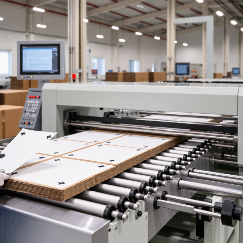
How to Calibrate Die Cutters for Register Accuracy in 2026?

Defining Register Accuracy in Die Cutting for 2026

In 2026, register accuracy should mean more than a clean-looking sample. It is the measured distance between the printed reference and the die-cut edge. Measure it in X and Y. Check angular drift, too. Repeatability matters most.

On a rotary die cutter, I record deviation across the lead edge, center, and tail. A 0.3 mm average error may hide a 0.8 mm tail error. Paper moisture, web tension, sheet squareness, and cylinder pressure can change the result. Even a strong first setup can wander during a long run. That is where calibration becomes practical, not theoretical.

The 2024 FEFCO statistics reported European corrugated output above 50 billion square metres annually. At that scale, tiny register errors create substantial waste.

Smithers’ The Future of Global Packaging to 2028 valued the worldwide packaging market at about 1.17 trillion US dollars in 2023. Its projected growth increases pressure for measurable quality control.

ISO 12647-2 supports process-control thinking for printed colour and image positioning, but it does not define die-cut register tolerance. That gap needs site-specific limits.

A useful 2026 specification should state tolerance, sampling frequency, measurement location, and acceptable repeatability. Camera systems help, but they are not infallible. Dust, glare, and weak registration marks can mislead operators. I still verify automated readings with a calibrated rule and a physical sample. My own imperfect lesson is simple: a single approved sheet proves almost nothing. Consistent results across the run prove more.

Preparing the Die Cutter and Materials for Calibration

Preparing the die cutter for register calibration starts with a stable machine, not a hurried test sheet. Lock out the press before cleaning the platen, cutting station, and guide surfaces. Remove paper dust and adhesive residue; even a thin deposit can shift a board or mask uneven pressure. Check that the die is seated flat and that clamps are secure. Inspect bearings, side lays, grippers, and waste-stripping components for play or damage. Record any adjustment. A machine that changes between test runs cannot provide trustworthy register readings.

Condition the actual production stock before testing. Stack it near the machine, protect it from drafts, and let it reach the room’s temperature and humidity. Measure several sheets, not just the top one. Flute, coating, moisture, and grain direction can affect feeding and dimensional stability. The Flexographic Technical Association’s FIRST 6.0 process-control guidance emphasizes controlling variables and documenting conditions; apply the same discipline to die-cut trials. Mark a clear crosshair on the printed sheet and measure its position against the cut edge at multiple points. Start with a small run. A 0.5 mm shift may look minor, but it can expose drift across a carton panel. That threshold is a shop check, not a universal industry tolerance. Recheck after each adjustment; I have seen teams skip this step, then blame the die for a feeder problem.

Preparing the Die Cutter and Materials for Register Calibration

Sample calibration readings show absolute register error at four sheet positions before and after setup checks. The 0.20 mm line is an example process target, not a universal machine specification.

Aligning Print, Die, and Feed Registration Systems

Accurate die cutting in 2026 depends on one coordinated registration system, not a single adjustment. Print, die, and feed registration must share the same reference point. Begin with a clean test sheet and mark the machine direction clearly. Measure the printed image against the intended die line at several positions. A small error at the lead edge can become a visible mismatch near the tail.

Experienced operators usually stabilize the feed before correcting the die station. Check web tension, side guides, nip pressure, and material curl. Then adjust print-to-feed timing with the machine running at production speed. Stop-and-start checks can mislead you. Use a registration camera or calibrated marks when available, but verify its readings with a steel rule and a loupe. Record every change. Guessing wastes substrate and hides repeatable problems.

Tips:

Calibrate after warm-up, not immediately after startup. Use the same material batch for testing. Check both left and right edges. If the error changes across the sheet, inspect skew or roller pressure before changing die timing. Leave a small tolerance for material movement. Perfect alignment on the first attempt is uncommon.

We once corrected the die when the real issue was a drifting feed sensor. That mistake reinforced a useful rule: confirm the reference before adjusting the cutter.

Testing Cut Accuracy and Correcting Alignment Errors

How to Calibrate Die Cutters for Register Accuracy in 2026?

Testing Cut Accuracy and Correcting Alignment Errors

Accurate die cutting begins with a controlled test sheet. Use the actual substrate, ink coverage, and production speed whenever possible. A clean setup can hide problems that appear during a real run.

Print a test grid with crosshair marks, corner targets, and a small reference circle. Check each cut under bright, even lighting. Measure the distance between the printed marks and cut edges with a calibrated ruler or digital gauge. Compare the left, right, top, and bottom positions. Uneven gaps often indicate web drift, feeder movement, or plate misalignment.

Correct one variable at a time. Adjust the feeder guides before changing the cutting station. If the error grows across the sheet, inspect material tracking and roller pressure. If every cut shifts equally, reset the register reference. Small corrections are safer than large changes. Run another test after each adjustment.

I once corrected a consistent side shift by moving the cutting head, but the real issue was a loose guide. That mistake wasted several sheets. It also showed why visual judgment is not enough. Record measurements, machine settings, and substrate conditions in a calibration log. A tolerance of 0.2 millimeters may suit one job, but not another. Keep checking after warm-up, because expansion can change alignment. Calibration is never perfectly static.

Maintaining Calibration Records and Long-Term Precision

How to Calibrate Die Cutters for Register Accuracy in 2026?
Maintaining Calibration Records and Long-Term Precision

Accurate registration depends on more than a well-adjusted die. Record the press speed, substrate lot, temperature, die position, and measured drift after each setup. ISO 12647-6:2020 provides process-control guidance for flexographic printing, including controlled measurement conditions. It is not a die-cut tolerance specification, so pair it with your own approved job tolerances. A simple record beats a perfect memory.

For each run, measure register at the same marked points on the sheet, using a calibrated loupe or vision system. Log results at setup, after changeovers, and at planned intervals during production. A practical starting point is to check every 500 sheets, then adjust that interval using actual drift and scrap data. Keep calibration dates, tool identification, operator, and corrective actions together. Patterns matter: repeated shifts toward one edge may indicate feed alignment, not a worn die. And yes, records can be tedious. Missing entries make root-cause reviews much harder.

Tips: Keep one reference sheet from each approved setup. Compare it with later samples under the same lighting and measurement method. Recheck after blade replacement, impact, or extended downtime. Review the log monthly; if drift keeps returning, investigate the process rather than repeatedly correcting the register.

How to Calibrate Die Cutters for Register Accuracy in 2026? - Maintaining Calibration Records and Long-Term Precision
Calibration Date Machine / Station ID Register Check Target Tolerance Pre-Adjustment Error Adjustment or Verification Action Post-Adjustment Error Result Next Check Due Record Reference
2026-01-12 Die Cutter DC-01 Print-to-cut, machine direction ±0.10 mm +0.18 mm Cleaned the registration sensor and corrected the web guide offset; verified with a 20-sample test run. +0.04 mm Adjusted — Pass 2026-02-12 CAL-2026-001
2026-02-12 Die Cutter DC-01 Print-to-cut, cross direction ±0.10 mm -0.06 mm Confirmed sensor alignment and checked the web tracking at operating speed; no adjustment required. -0.06 mm Pass 2026-03-12 CAL-2026-002
2026-03-10 Die Cutter DC-02 Print-to-cut, machine direction ±0.10 mm +0.12 mm Re-zeroed the registration mark sensor and verified cut position using a calibrated measuring scale and repeat samples. +0.03 mm Adjusted — Pass 2026-04-10 CAL-2026-003
2026-04-10 Die Cutter DC-02 Print-to-cut, cross direction ±0.10 mm +0.02 mm Checked sensor bracket security, web tension, and registration repeatability across 20 consecutive samples. +0.02 mm Pass 2026-05-11 CAL-2026-004
2026-05-11 Die Cutter DC-01 Print-to-cut, machine direction ±0.10 mm -0.14 mm Inspected the registration sensor mount, secured a loose fastener, and repeated the test after stabilizing web tension. -0.05 mm Adjusted — Pass 2026-06-11 CAL-2026-005
2026-06-11 Die Cutter DC-01 Print-to-cut, cross direction ±0.10 mm +0.07 mm Verified alignment at normal production speed and reviewed the recent register-error trend; no adjustment required. +0.07 mm Pass — Monitor 2026-07-11 CAL-2026-006
2026-07-10 Die Cutter DC-02 Print-to-cut, machine direction ±0.10 mm +0.21 mm Cleaned the sensor lens, corrected the sensor position, and confirmed the result with repeat measurements after setup. +0.06 mm Adjusted — Pass 2026-08-10 CAL-2026-007
2026-08-10 Die Cutter DC-02 Print-to-cut, cross direction ±0.10 mm -0.03 mm Checked registration stability at the start and end of a 30-minute run; no drift requiring adjustment was observed. -0.03 mm Pass 2026-09-10 CAL-2026-008
2026-09-10 Die Cutter DC-01 Print-to-cut, machine direction ±0.10 mm +0.09 mm Confirmed calibration using the same approved reference method; logged the reading for trend review. +0.09 mm Pass — Monitor 2026-10-12 CAL-2026-009
2026-10-12 Die Cutter DC-01 Print-to-cut, cross direction ±0.10 mm -0.04 mm Verified sensor response and checked web tracking across the working width; no adjustment required. -0.04 mm Pass 2026-11-12 CAL-2026-010
2026-11-12 Die Cutter DC-02 Print-to-cut, machine direction ±0.10 mm +0.11 mm Rechecked setup and sensor alignment; adjusted the register offset and repeated the verification test. +0.03 mm Adjusted — Pass 2026-12-14 CAL-2026-011
2026-12-14 Die Cutter DC-02 Print-to-cut, cross direction ±0.10 mm +0.01 mm Completed end-of-year verification and reviewed calibration history for recurring drift or adjustment patterns. +0.01 mm Pass 2027-01-14 CAL-2026-012
Recordkeeping and precision notes: The ±0.10 mm limit shown is an example internal process target, not a universal industry tolerance; set acceptance limits according to the product drawing and validated process requirements. Record the reference method or instrument, its identification and calibration status, operator, material and running conditions, sample count, readings, adjustments, and approval with each check. Use consistent measurement methods for trend comparisons, and review repeated near-limit results for possible sensor, web-tension, tooling, or setup drift.

FAQS

Why should the die cutter be cleaned before register calibration?

Paper dust and adhesive can shift the board or hide uneven pressure. Clean the platen, cutting station, and guide surfaces before testing.

What should operators inspect before running calibration sheets?

Check that the die sits flat and its clamps are secure. Inspect bearings, side lays, grippers, and waste-stripping parts for looseness or damage.

How should production stock be prepared for calibration?

Keep the actual stock near the machine, away from drafts, until it reaches room conditions. Measure several sheets because moisture and flute can affect feeding.

How can register drift be measured?

Mark a crosshair on the printed sheet. Measure its position against the cut edge at several points using the same method each time.

Is a 0.5 mm shift an acceptable tolerance?

Not universally. It is a shop check that may reveal drift across a carton panel, but approved job tolerances should guide decisions.

What information belongs in a calibration record?

Log press speed, stock lot, temperature, die position, measured drift, tool identification, operator, and corrective actions. A simple record helps.

How often should register be checked during production?

A practical starting point is every 500 sheets. Adjust the interval based on actual drift and scrap data.

What might repeated shifts toward one sheet edge indicate?

They may point to feed alignment rather than a worn die. Repeatedly correcting the register without investigating can miss the real cause.

When should calibration be rechecked?

Recheck after blade replacement, an impact, or extended downtime. Keep an approved reference sheet for comparison.

Why are calibration records sometimes difficult to use?

Missing entries make root-cause reviews harder. It can feel tedious, but consistent records reveal patterns over time.

Conclusion

Achieving register accuracy in die cutting in 2026 requires precise coordination between the printed artwork, die position, and material feeding system. The process begins by preparing the die cutter, checking tooling condition, selecting stable materials, and controlling environmental factors that may affect sheet movement. Operators should then align print marks, feed guides, sensors, and die-cutting components so every sheet follows the same reference position. Understanding how to calibrate a high speed flatbed die-cutter for register accuracy helps reduce dimensional variation and supports consistent production at higher speeds.

After initial alignment, test sheets should be measured across multiple points to identify shifts, skew, stretch, or uneven pressure. Small adjustments to guides, timing, sensor settings, and die placement can correct these errors before full production begins. Calibration records should document material specifications, machine settings, test results, and corrective actions. Regular inspections and scheduled recalibration help preserve long-term precision, minimize waste, and maintain dependable cutting quality as equipment and production conditions change.

Mason

Mason

Mason is a seasoned marketing professional with a deep expertise in the company's offerings and a passion for driving brand awareness. With a strong background in digital marketing strategies, he has an innate ability to connect with diverse audiences and effectively communicate product benefits.......